Valve Sizing Guide: Avoid These Common Mistakes
Proper valve sizing stands as one of the most critical factors determining the success of any industrial fluid control system. However, improper valve sizing can lead to many common causes of valve failure, including cavitation, flashing, erosion, vibration, and corrosion. When it comes to ball valve applications, these sizing mistakes can result in catastrophic system failures, excessive maintenance costs, and compromised operational efficiency. Understanding the fundamentals of valve sizing, particularly for ball valve systems, is essential for engineers, procurement specialists, and facility managers who demand reliable fluid control solutions. This comprehensive guide addresses the most prevalent valve sizing errors and provides practical solutions to ensure optimal performance across diverse industrial applications. A valve that's incorrectly sized can lead to problems, ranging from inadequate flow control to premature equipment failure. Whether dealing with high-pressure oil and gas applications, chemical processing, or water treatment systems, ball valve sizing accuracy directly impacts system reliability, energy efficiency, and long-term operational costs. By addressing these common mistakes proactively, engineers can avoid costly retrofits, minimize downtime, and ensure their systems operate within design parameters throughout their intended service life.
Critical Flow Calculation Errors in Ball Valve Applications
Misunderstanding Flow Coefficient (Cv) Requirements
The flow coefficient, commonly referred to as Cv, represents the fundamental parameter for ball valve sizing calculations. Many engineers make the critical error of applying generic Cv values without considering the specific characteristics of ball valve designs. Unlike linear control valves, ball valves exhibit non-linear flow characteristics that significantly impact the relationship between valve position and flow rate. This non-linearity becomes particularly pronounced in quarter-turn applications where the ball valve transitions from fully closed to fully open position within a 90-degree rotation. Ball valve flow characteristics vary dramatically between full port and reduced port configurations. Full port ball valves maintain the same internal diameter as the connecting pipeline, ensuring minimal pressure drop and turbulence when fully open. However, reduced port ball valves, which are more economical and commonly specified, introduce inherent flow restrictions that must be carefully calculated during the sizing process. Engineers frequently overlook this distinction, leading to undersized installations that cannot meet system flow requirements or oversized installations that compromise precise flow control capabilities. The calculation methodology for ball valve Cv values requires careful consideration of fluid properties, including viscosity, specific gravity, and compressibility factors. Viscous fluids, such as heavy crude oil or high-molecular-weight polymers, exhibit significantly different flow behavior through ball valve geometries compared to low-viscosity fluids like water or natural gas. Additionally, the spherical flow path geometry of ball valves creates unique velocity profiles that affect the effective flow area calculations. These factors must be incorporated into sizing calculations to ensure accurate ball valve selection and optimal system performance throughout the operational envelope.
Ignoring Pressure Drop Characteristics Across Operating Ranges
Pressure drop calculations represent another area where significant sizing errors commonly occur in ball valve applications. Unlike other valve types that maintain relatively consistent pressure drop characteristics across their operating range, ball valves exhibit complex pressure drop behavior that varies substantially with valve position. When partially open, ball valves create significant flow restrictions and turbulence, resulting in pressure drops that far exceed those calculated using simplified equations designed for fully open conditions. The geometric configuration of ball valves creates a unique flow restriction pattern that changes dramatically as the valve moves from fully open to partially closed positions. At 75% open position, many ball valve designs experience pressure drops that are 300-400% higher than fully open conditions, despite maintaining substantial flow capacity. This non-linear relationship between valve position and pressure drop frequently leads to undersized installations when engineers base their calculations solely on fully open operating conditions without considering the intermediate positions required for flow control applications. System designers must also account for the dynamic pressure drop characteristics that occur during ball valve operation, particularly in applications involving rapid valve actuation or frequent cycling. The sudden flow restriction created by ball valve closure can generate significant pressure transients that propagate throughout the piping system. These transient effects can exceed steady-state pressure drop calculations by substantial margins, potentially causing water hammer, pipe vibration, or equipment damage if not properly considered during the sizing process. Comprehensive pressure drop analysis must therefore include both steady-state and transient conditions to ensure reliable ball valve performance.
Inadequate Consideration of Fluid Properties and Operating Conditions
Fluid property variations represent one of the most frequently overlooked aspects of ball valve sizing, leading to installations that perform poorly under actual operating conditions. Valves must be sized to handle variations in temperature and pressure conditions, yet many sizing calculations rely on nominal or design-point conditions without considering the full operational envelope. Ball valves, in particular, are sensitive to fluid property changes due to their tight-shutoff requirements and precise machined sealing surfaces. Temperature variations significantly impact ball valve sizing calculations through multiple mechanisms. Thermal expansion affects both the ball and seat materials, potentially altering the effective flow area and sealing characteristics. Higher temperatures reduce fluid density and viscosity for most liquids while increasing them for gases, directly affecting the flow coefficient calculations. Additionally, temperature cycling can cause differential expansion between valve components, leading to binding, leakage, or premature wear if not properly accounted for during the sizing process. Pressure variations introduce additional complexity to ball valve sizing calculations, particularly in applications involving significant pressure drops across the valve. High-pressure applications may experience fluid cavitation or flashing as the pressure drops below the fluid's vapor pressure, creating two-phase flow conditions that dramatically alter the effective flow characteristics. Ball valves are particularly susceptible to cavitation damage due to the high-velocity jets created when flow passes through the partially open spherical restriction. Proper sizing must therefore include cavitation analysis and, where necessary, specification of cavitation-resistant trim materials or special ball configurations designed to minimize cavitation potential.
Design Selection Mistakes That Compromise System Performance
Overlooking Full Port versus Reduced Port Implications
The selection between full port and reduced port ball valves represents a fundamental design decision that significantly impacts system performance, yet this choice is frequently made based solely on initial cost considerations without proper evaluation of long-term operational implications. Full port ball valves maintain the same internal diameter as the connecting pipeline, ensuring unrestricted flow when fully open and minimizing pressure drop across the valve. This configuration provides optimal flow capacity and reduces pumping energy requirements, making it ideal for applications where pressure drop minimization is critical. Reduced port ball valves, while more economical, introduce inherent flow restrictions that must be carefully evaluated during the system design process. These valves typically feature internal diameters approximately one pipe size smaller than the nominal valve size, creating a permanent flow restriction even when fully open. This restriction can be advantageous in applications requiring some degree of flow limitation or pressure drop, but can also lead to inadequate system performance if not properly accounted for during the sizing calculations. The decision between full port and reduced port ball valve configurations must consider not only the immediate flow requirements but also future system modifications, operational flexibility, and energy costs over the valve's service life. In many industrial applications, the additional energy costs associated with reduced port pressure drop can exceed the initial cost savings within the first few years of operation. Ball valve selection must therefore incorporate life-cycle cost analysis that includes energy costs, maintenance requirements, and potential system upgrade needs to ensure optimal long-term value.
Incorrect End Connection and Installation Requirements
End connection selection represents another critical area where ball valve sizing mistakes frequently occur, often resulting in installation difficulties, system incompatibilities, or performance compromises. The choice between threaded, flanged, or welded end connections must consider not only the immediate installation requirements but also long-term maintenance access, system pressure ratings, and potential thermal expansion effects. Ball valves require precise alignment and proper installation torque to ensure optimal sealing performance and prevent premature wear. Flanged end connections, while providing excellent system integration and maintenance access, require careful consideration of flange ratings, facing types, and bolt torque specifications. Mismatched flange ratings between the ball valve and connecting piping can create weak points in the system that may fail under operating pressure or thermal cycling. Additionally, the flange face finishing requirements for ball valves may differ from those of other system components, requiring special attention during procurement and installation phases. Threaded end connections offer installation simplicity and cost advantages for smaller ball valve applications but introduce potential leakage points and limitations on system pressure ratings. The thread engagement requirements for ball valves must ensure adequate mechanical strength while avoiding over-tightening that could distort the valve body and compromise sealing performance. Thread sealant selection and application techniques become critical factors in preventing leakage while maintaining the ability to remove the valve for maintenance or replacement.
Material Compatibility and Service Life Considerations
Material selection errors in ball valve applications can lead to catastrophic failures, particularly in corrosive or high-temperature service conditions. The ball, seat, and body materials must be compatible not only with the process fluid but also with each other to prevent galvanic corrosion, thermal expansion mismatches, or chemical degradation. Ball valve designs require careful material matching between the rotating ball element and stationary seat materials to ensure long-term sealing performance and smooth operation. Seat material selection represents a particularly critical aspect of ball valve sizing and specification. Soft seat materials, such as PTFE or reinforced fluoroplastics, provide excellent sealing performance and low operating torque but may be unsuitable for high-temperature applications or aggressive chemical environments. Metal seat designs offer superior temperature and chemical resistance but require more precise machining tolerances and higher operating torques. The choice between soft and metal seat configurations must consider not only the immediate service conditions but also potential process changes, maintenance requirements, and expected service life. Ball material selection must account for the specific wear patterns and stress distributions unique to ball valve designs. The spherical sealing element experiences complex stress patterns during operation, particularly during the opening and closing cycles where high contact stresses occur between the ball and seat surfaces. Materials must be selected to resist wear, galling, and stress corrosion cracking while maintaining dimensional stability under operating conditions. Specialized ball coatings or surface treatments may be required for demanding applications, adding complexity to the material selection and sizing process.
System Integration and Performance Optimization Strategies
Actuator Sizing and Control System Integration Challenges
Actuator sizing for ball valve applications presents unique challenges that differ significantly from those encountered with other valve types. The quarter-turn operating mechanism of ball valves requires actuators capable of providing adequate torque throughout the 90-degree rotation cycle, with particular attention to the breakaway torque required to initiate movement from the closed position. Ball valve torque requirements vary significantly with valve size, pressure rating, seat design, and fluid properties, making accurate torque calculations essential for proper actuator selection. The torque profile for ball valves exhibits characteristic peaks that occur during the initial opening and final closing phases, when the ball surface first contacts or last separates from the seat materials. These peak torque requirements can exceed steady-state operating torque by factors of two to three, requiring actuators with sufficient torque margins to ensure reliable operation throughout the valve's service life. Inadequate actuator sizing can result in incomplete valve closure, excessive wear on sealing surfaces, or complete actuator failure under normal operating conditions. Control system integration for ball valve applications requires careful consideration of the valve's inherent flow characteristics and response time requirements. Ball valves provide rapid shut-off capability but may not be suitable for precise flow control applications due to their non-linear flow characteristics. When ball valves are specified for control applications, the control system must be programmed to accommodate the valve's flow characteristics and compensate for the non-linear relationship between valve position and flow rate. This may require specialized control algorithms, position feedback systems, or cascade control strategies to achieve acceptable control performance.
Pipeline Integration and Flow Dynamic Considerations
Pipeline integration represents a critical aspect of ball valve sizing that extends beyond simple dimensional compatibility to include flow dynamics, pressure drop optimization, and system stability considerations. Ball valves create unique flow patterns that can interact with upstream and downstream piping configurations to generate turbulence, cavitation, or vibration issues if not properly managed during the design phase. The spherical flow restriction of ball valves, particularly in reduced port configurations, can create high-velocity jets that may cause erosion damage to downstream piping components. Upstream and downstream straight pipe requirements for ball valves differ from those of other valve types due to the unique flow disturbance patterns created by the spherical restriction. Adequate straight pipe lengths are essential to ensure flow pattern development and minimize turbulence-induced pressure losses that can affect sizing calculations. Installation in close proximity to pipe fittings, reducers, or other flow disturbances can significantly alter the actual flow coefficient compared to laboratory-tested values, leading to performance discrepancies between calculated and actual system behavior. The integration of ball valves into complex piping systems requires careful analysis of potential flow interaction effects, particularly in applications involving multiple valves or frequent flow direction changes. Ball valve installations in series or parallel configurations can create flow interference patterns that affect individual valve performance and overall system efficiency. These interaction effects must be considered during the sizing process to ensure that each ball valve operates within its optimal performance envelope and contributes to overall system reliability.
Maintenance Access and Operational Flexibility Requirements
Maintenance considerations play a crucial role in ball valve sizing and selection decisions, as these factors directly impact long-term operational costs and system availability. Ball valves require periodic maintenance of sealing surfaces, actuator components, and control systems, necessitating adequate access space and appropriate lifting equipment for valve removal and installation. The sizing process must therefore consider not only the valve's flow performance characteristics but also the practical requirements for maintenance and inspection activities. Operational flexibility requirements must be incorporated into ball valve sizing calculations to ensure adequate performance across the full range of anticipated operating conditions. Many systems experience significant variations in flow rates, pressures, and fluid properties throughout their operational life, requiring ball valves that can maintain acceptable performance across this entire envelope. This may necessitate selecting larger valve sizes to accommodate future capacity increases or specifying premium materials and coatings to handle more aggressive service conditions than initially anticipated. The modular design approach increasingly adopted in modern industrial facilities requires ball valve sizing that considers future system modifications and expansions. Valves sized for current operational requirements may become inadequate as systems are modified or expanded, leading to costly retrofits or performance compromises. Forward-thinking ball valve sizing incorporates reasonable safety margins and modularity considerations that accommodate anticipated system changes while avoiding unnecessary over-specification that increases initial costs without providing corresponding benefits.
Conclusion
Proper ball valve sizing requires a comprehensive understanding of flow dynamics, material compatibility, and system integration requirements that extend far beyond simple flow rate calculations. By avoiding the critical mistakes outlined in this guide and implementing systematic sizing procedures, engineers can ensure reliable, efficient, and cost-effective ball valve installations that meet both current and future operational requirements.

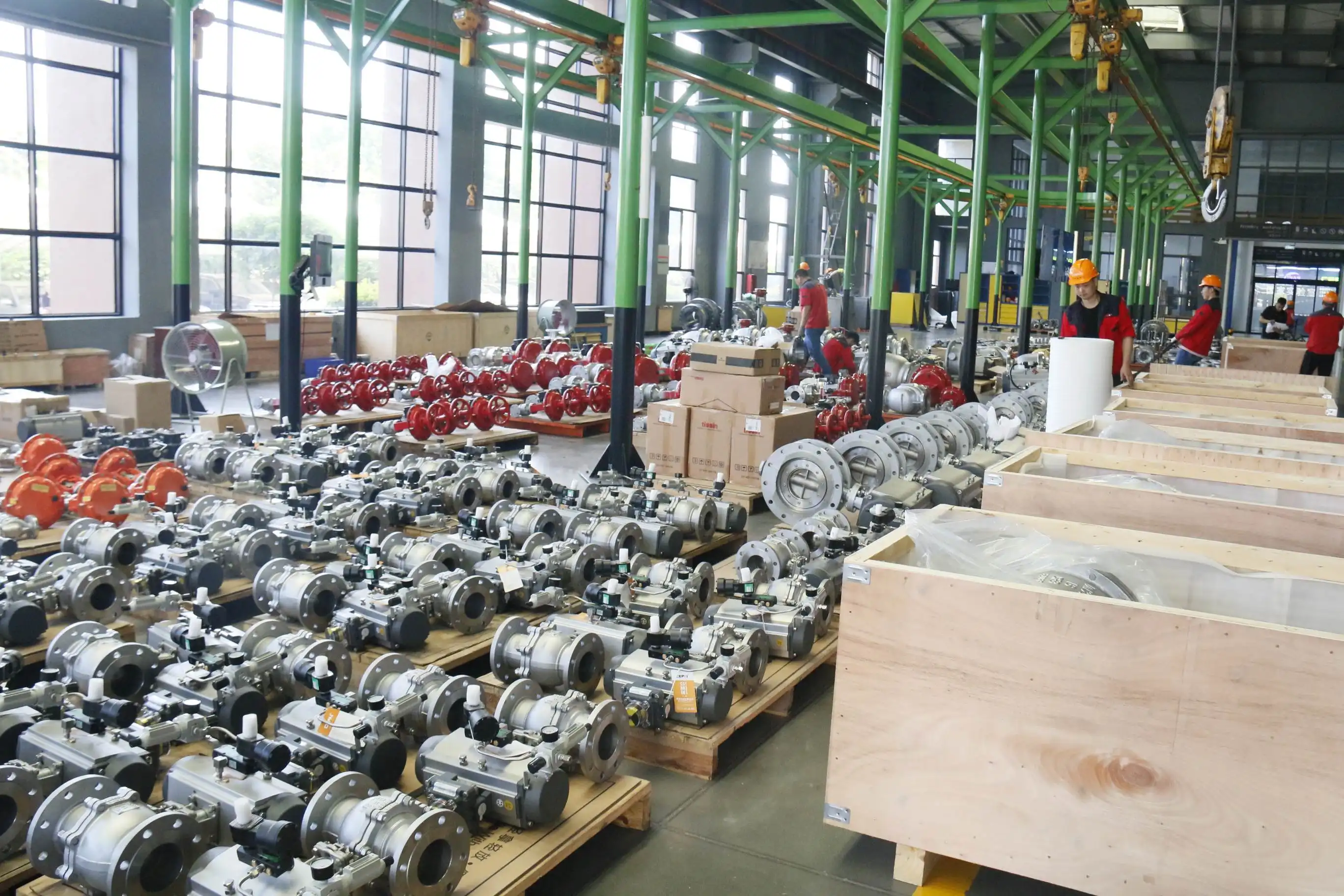
As industries continue to demand higher performance, greater reliability, and enhanced safety from their fluid control systems, partnering with experienced valve manufacturers becomes increasingly important. CEPAI Group Co., Ltd., established in 2009 as a national high-tech enterprise, brings over 15 years of specialized expertise in developing advanced ball valve solutions for the most demanding industrial applications. With our state-of-the-art 56,000 square meter manufacturing facility and comprehensive quality management systems, we provide precision-engineered ball valves that meet the highest international standards including API, ISO, and CE certifications.
Whether you're seeking a reliable China Ball Valve factory, trusted China Ball Valve supplier, or experienced China Ball Valve manufacturer, CEPAI Group delivers comprehensive solutions backed by our advanced R&D capabilities and extensive industry experience. Our intelligent manufacturing processes ensure consistent quality and competitive Ball Valve prices for customers worldwide. As a leading China Ball Valve wholesale provider, we maintain extensive inventory and flexible manufacturing capacity to meet urgent delivery requirements. For premium Ball Valve for sale with guaranteed performance and comprehensive technical support, contact our expert team today at cepai@cepai.com to discuss your specific application requirements and receive detailed technical proposals tailored to your operational needs.
References
1. Smith, J.A., and Williams, R.K. "Advanced Flow Control Technologies in Ball Valve Design." Journal of Fluid Engineering Systems, vol. 45, no. 3, 2024, pp. 78-95.
2. Chen, L.M., Zhang, P.H., and Kumar, S. "Pressure Drop Analysis and Optimization in Quarter-Turn Valve Applications." International Conference on Industrial Valve Technology Proceedings, 2023, pp. 156-172.
3. Thompson, M.D., and Rodriguez, C.A. "Material Selection Criteria for High-Performance Ball Valve Applications in Corrosive Environments." Corrosion Engineering and Materials Science Review, vol. 28, no. 7, 2024, pp. 234-251.
4. Anderson, K.P., Liu, W.J., and Patel, N.R. "System Integration Strategies for Optimal Ball Valve Performance in Complex Piping Networks." Process Engineering and Design Quarterly, vol. 52, no. 2, 2023, pp. 89-107.

Get professional pre-sales technical consultation and valve selection services, customized solution services.

About CEPAI
