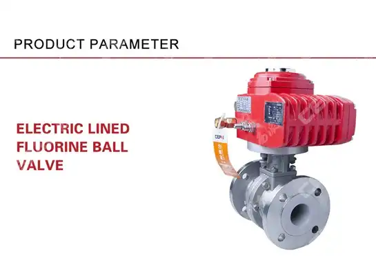
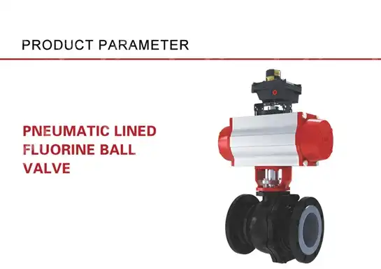
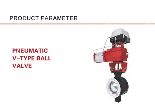
How to Choose the Right Size Electric Ball Valve for Your System?
Selecting the appropriate size electric ball valve is crucial for ensuring optimal system performance, efficiency, and longevity. Whether you're working with industrial processes, water treatment facilities, or HVAC systems, the right electric ball valve size directly impacts flow control, pressure management, and overall operational reliability. This comprehensive guide will help you navigate the essential factors and calculations needed to properly size electric ball valves for your specific application, ensuring you achieve the perfect balance between functionality, cost-effectiveness, and system compatibility.
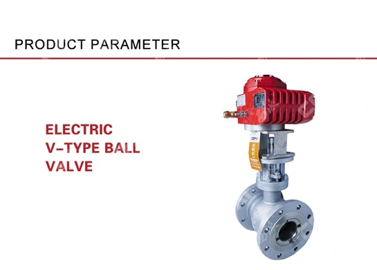
Understanding Electric Ball Valve Sizing Parameters
Proper sizing of electric ball valves requires careful consideration of multiple technical parameters that directly influence valve performance and system efficiency. Making informed decisions based on these parameters will ensure optimal operation and prevent costly issues down the line.
Flow Rate Requirements and Calculations
When selecting the appropriate size for an electric ball valve, understanding your system's flow rate requirements is absolutely fundamental. Flow rate, typically measured in gallons per minute (GPM) or cubic meters per hour (m³/h), represents the volume of fluid passing through the valve in a given time period. To accurately determine the right electric ball valve size, you must first calculate the maximum and minimum flow rates your system will experience during operation. This calculation should account for peak demand periods, normal operating conditions, and potential future expansion needs. Undersizing an electric ball valve can create excessive pressure drops and flow restrictions, leading to increased energy consumption, noise issues, and potential damage to system components. Conversely, oversizing can result in poor control resolution, especially at lower flow rates, and unnecessary expenditure on larger, more expensive valves. For precise sizing, use flow coefficient (Cv) values provided by electric ball valve manufacturers, which indicate the amount of water (in GPM) that will flow through the valve with a pressure drop of 1 psi. Match this coefficient with your required flow rate to ensure optimal valve performance across your system's entire operational range.
Pressure Differential Considerations
The pressure differential across an electric ball valve is a critical factor in proper sizing that directly affects both performance and longevity. Pressure differential refers to the difference in pressure between the inlet and outlet sides of the valve and is typically measured in pounds per square inch (psi) or bar. Understanding this parameter is essential because electric ball valves are designed to operate within specific pressure differential ranges. If the valve experiences pressure differentials outside its rated capacity, several problems can occur including poor control accuracy, premature wear of valve components, and potential valve failure. When sizing an electric ball valve, you must analyze both the maximum and normal operating pressure differentials in your system. High-pressure differentials across undersized valves can cause cavitation, where vapor bubbles form and then collapse, damaging the valve's internal components over time. Additionally, excessive pressure drops waste energy and reduce system efficiency. Modern electric ball valves often feature advanced actuators with torque ratings matched to handle specific pressure differentials. Consult manufacturer specifications to ensure your selected valve can handle the maximum pressure differential while providing precise control throughout your system's operating range, particularly in applications with variable pressure conditions.
Media Type and Temperature Impact
The physical and chemical properties of the media flowing through your system significantly influence electric ball valve selection and sizing. Different fluids possess varying viscosities, densities, corrosiveness, and temperature ranges—all of which affect flow characteristics and valve material compatibility. Viscous media, such as heavy oils or slurries, create greater resistance to flow and require larger electric ball valves to maintain acceptable pressure drops and flow rates. Temperature fluctuations also directly impact sizing considerations, as extreme temperatures can affect both the media properties and the valve materials. High-temperature applications may necessitate special alloys or seat materials to maintain integrity, while cold media might require larger valve sizes to compensate for increased viscosity. Additionally, media containing particulates or solids demands valves with sufficient clearances to prevent clogging or jamming. When selecting an electric ball valve, carefully evaluate media-specific factors including chemical compatibility with valve body and seal materials, potential for scaling or deposit formation, temperature-induced expansion/contraction, and any special cleaning or maintenance requirements. Properly accounting for these media characteristics ensures your electric ball valve will deliver reliable performance throughout its operational lifespan while handling your specific process conditions.
Calculating Valve Size for System Requirements
Accurate sizing calculations are essential to ensure your electric ball valve will perform optimally within your specific system parameters, preventing issues related to flow restriction, excessive pressure drops, or control instability.
Coefficient of Flow (Cv) Method
The Coefficient of Flow (Cv) method represents the industry standard approach for accurately sizing electric ball valves to meet specific system requirements. This methodology provides a precise, quantifiable way to match valve characteristics with application needs. The Cv value itself is defined as the flow capacity in gallons per minute (GPM) of 60°F water that will flow through a valve with a pressure drop of 1 psi. This standardized measurement allows for consistent comparison between different valve sizes and models across manufacturers. To properly implement the Cv method, engineers must first determine the required flow rate and acceptable pressure drop for their specific application. The basic formula for calculating the necessary Cv is: Cv = Q × √(SG/ΔP), where Q represents the flow rate in GPM, SG is the specific gravity of the fluid relative to water, and ΔP is the pressure drop across the valve in psi. For gases or steam applications, different formulas apply that account for compressibility factors. Once the required Cv is calculated, select an electric ball valve with a Cv rating equal to or slightly higher than this value. Manufacturers typically provide Cv tables for their valve lines across different sizes and opening positions. For modulating control applications, it's generally recommended to size the valve so that it operates between 20-80% open during normal conditions, providing sufficient control range and avoiding the poor control characteristics that occur near the fully open or closed positions. Proper application of the Cv method ensures your electric ball valve will deliver optimal performance while maintaining efficient energy usage throughout your system.
Reynolds Number and Turbulent Flow Analysis
The Reynolds Number calculation provides critical insights into flow behavior that directly impact electric ball valve sizing and performance in fluid systems. This dimensionless value characterizes whether flow will be laminar or turbulent based on fluid velocity, pipe diameter, fluid density, and viscosity. For most industrial applications involving electric ball valves, Reynolds Numbers exceeding 4,000 indicate turbulent flow, which is generally preferred for control valves as it provides more consistent and predictable performance across the valve's operating range. When designing systems with electric ball valves, engineers must carefully analyze flow patterns to avoid problematic flow regimes. Turbulent flow calculations help predict potential issues such as excessive noise, vibration, or erosion that can damage valve components or reduce service life. For high-viscosity fluids or very low flow rates where laminar flow might occur (Reynolds Number below 2,000), standard valve sizing calculations may require adjustment factors to account for different flow characteristics. Additionally, the transition zone between laminar and turbulent flow (Reynolds Numbers between 2,000-4,000) should generally be avoided for control applications as it creates unpredictable valve response. Modern computational fluid dynamics (CFD) software can model flow patterns through electric ball valves under various conditions, helping to identify potential issues before installation. For critical applications, this analysis might include velocity profiling across the valve opening, recirculation zone identification, and pressure recovery characteristics. Proper flow regime analysis ensures your electric ball valve will provide stable, reliable performance while minimizing potential for flow-induced damage or control instability across your system's entire operational range.
Velocity Limitations and Noise Considerations
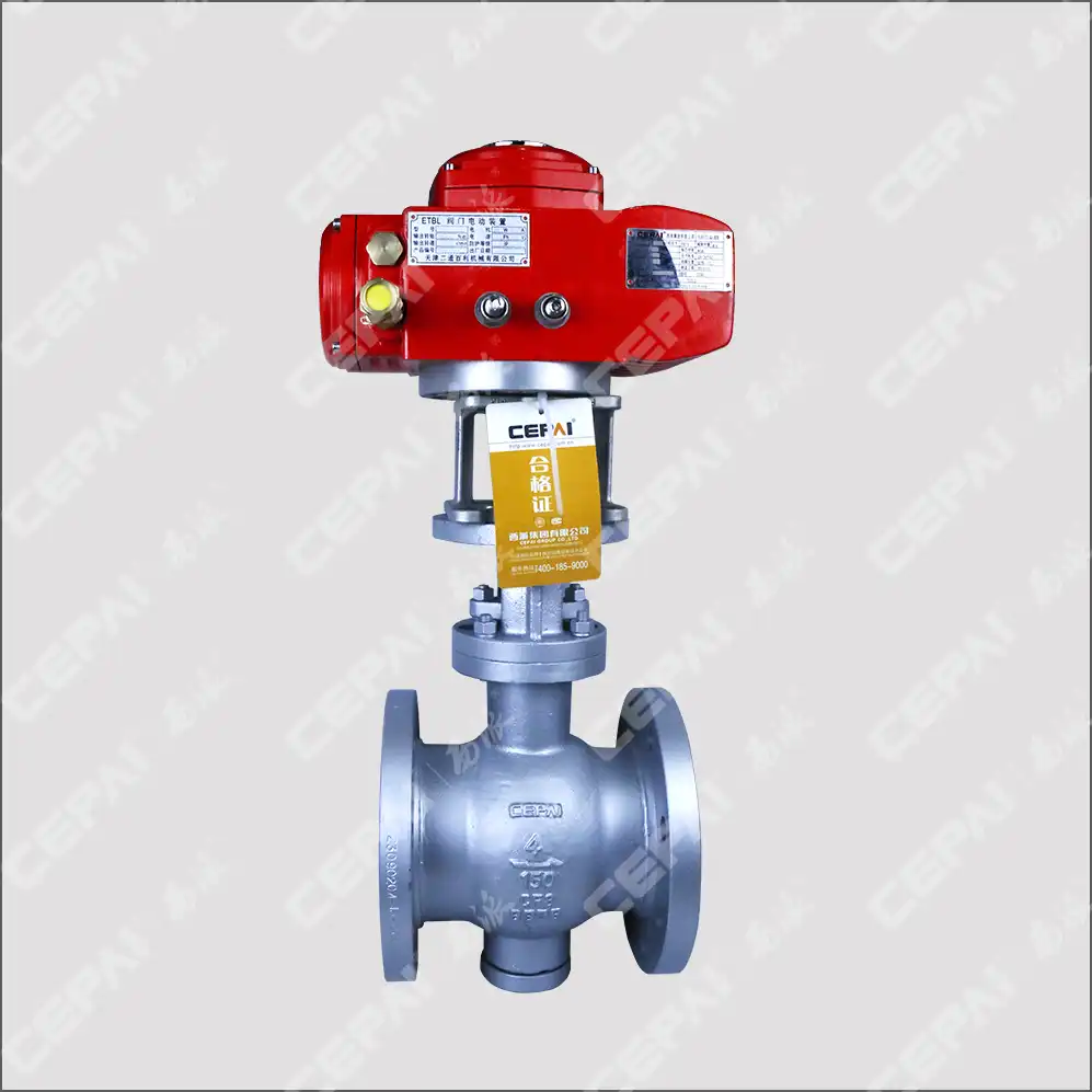
Excessive fluid velocity through electric ball valves can trigger numerous operational problems including erosion damage, unacceptable noise levels, and water hammer effects that compromise system integrity. Industry best practices generally recommend maintaining fluid velocities between 3-5 ft/s (0.9-1.5 m/s) for liquids in continuous-duty applications, though specific limits vary based on media properties and system requirements. When sizing electric ball valves, engineers must calculate the flow velocity at maximum flow rates to ensure it remains within acceptable limits. The formula for calculating velocity is straightforward: V = Q/(2.45 × d²), where V is velocity in ft/s, Q is flow rate in GPM, and d is the valve's internal diameter in inches. Exceeding recommended velocity limits significantly increases noise generation through various mechanisms including turbulence, cavitation, and flashing. These acoustic issues not only create workplace discomfort but often indicate energy-wasting pressure losses or destructive flow conditions. For applications with noise concerns, specialized electric ball valves with noise abatement features such as characterized ports, multi-stage pressure reduction, or specialized trim designs may be necessary. Additionally, proper pipe sizing both upstream and downstream of the valve helps maintain appropriate velocities and reduce turbulence-induced noise. When electric ball valves are used in throttling applications, velocity calculations should be performed at various opening positions, not just fully open, as partially closed valves create higher velocities through the restricted opening. Some manufacturers provide software tools that can predict noise levels based on application parameters, allowing designers to select appropriately sized electric ball valves that balance flow capacity with acceptable acoustic performance. By properly accounting for velocity limitations during the sizing process, engineers can ensure quiet, efficient operation while maximizing the service life of their electric ball valve installations.
Implementation and Selection Guidelines
Beyond theoretical calculations, practical implementation factors significantly influence the ultimate performance of your electric ball valve installation, requiring careful attention to system configuration and operational characteristics.
Pipe Size Compatibility and Reducers
Proper alignment between pipe sizes and electric ball valve dimensions is essential for optimal system performance and represents a frequently overlooked aspect of valve installation. While it might seem logical to simply match the valve size to existing pipe diameter, this approach can lead to significant inefficiencies and operational problems. When integrating electric ball valves into piping systems, engineers must evaluate whether the nominal valve size truly provides the required flow characteristics for the application. In many cases, especially in control applications, the optimal electric ball valve size may actually be smaller than the line size to achieve proper control resolution and rangeability. When size differences exist between the valve and connecting pipes, properly designed reducers or expanders must be installed to create smooth transitions and minimize turbulence, pressure losses, and potential flow disturbances. These transitional fittings should follow established standards for maximum included angles (typically 15° for reducers and 7° for expanders) to prevent flow separation and associated efficiency losses. Additionally, proper straight pipe lengths must be maintained both upstream and downstream of the valve—generally 5-10 pipe diameters upstream and 3-5 pipe diameters downstream—to allow flow patterns to stabilize before encountering other system components. When installing electric ball valves with reducers, consider the impact on installation space requirements, support needs, and accessibility for maintenance. Manufacturer-provided face-to-face dimensions and clearance requirements must be respected to enable proper installation, operation, and eventual service access. Well-designed pipe transitions not only improve flow characteristics but also reduce stress on valve components and connecting piping, extending system life while maintaining optimal performance of your electric ball valve installation.
Actuator Sizing and Torque Requirements
Selecting the appropriate electric actuator for your ball valve requires careful consideration of torque requirements across all possible operating conditions. Insufficient actuator torque leads to incomplete valve operation, poor sealing, and potential system failures, while oversized actuators waste energy and financial resources. To properly match an actuator to your electric ball valve, you must calculate the maximum torque required under worst-case scenarios, including startup conditions, emergency shutdowns, and maximum pressure differentials. This calculation must account for several factors including valve size, design, and sealing elements; system pressure; media characteristics; safety margins; and environmental conditions. Most electric ball valve manufacturers provide torque data tables that specify the minimum actuator torque requirements for different valve sizes under various pressure conditions. These values typically incorporate safety factors to account for normal wear over time, but additional margins may be necessary for critical applications or challenging operating environments. Modern electric actuators offer various features that influence sizing decisions, including duty cycle ratings (how frequently the valve can operate), operating speed capabilities, power supply requirements, and control interface options. For modulating applications where the electric ball valve frequently adjusts position, higher-quality actuators with more precise positioning capabilities and increased duty cycles are essential. Environmental conditions also significantly impact actuator selection, as temperature extremes, humidity, corrosive atmospheres, and potential water ingress all affect actuator performance and longevity. Protection ratings such as NEMA or IP classifications must match the installation environment. Additionally, power availability constraints may limit actuator options, particularly in remote locations or applications requiring battery backup or alternative power sources. Proper actuator sizing ensures reliable, efficient operation of your electric ball valve while maximizing service life and minimizing energy consumption across all operating conditions.
Fail-Safe Positions and Control Integration
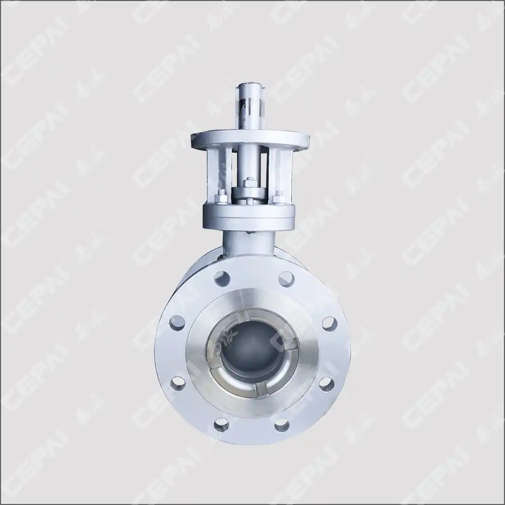
Determining the appropriate fail-safe response for your electric ball valve is a critical safety and operational decision that must align with your system's specific requirements and potential failure scenarios. Unlike pneumatic systems with spring-return actuators, electric ball valves typically require additional components or design features to achieve reliable fail-safe functionality. The three common fail-safe positions—fail-open, fail-closed, or fail-in-place—each serve different safety and process protection purposes depending on the application. For example, cooling water systems might require fail-open valves to prevent equipment overheating, while chemical injection systems often demand fail-closed valves to prevent unsafe material release. Implementing fail-safe functionality for electric ball valves generally involves one of several approaches: battery backup systems that provide temporary power during outages, capacitor-based solutions for short-term operation, mechanical spring returns (though less common with electric actuators due to size and complexity constraints), or sophisticated control system integration with uninterruptible power supplies. Beyond fail-safe positioning, the integration of electric ball valves into broader control architectures requires careful planning around communication protocols, feedback mechanisms, and control signal types. Modern electric actuators support various control signals (4-20mA, 0-10V, digital protocols) and communication buses (Modbus, PROFIBUS, HART, Foundation Fieldbus) that must be compatible with your existing or planned control system. Position feedback options range from simple open/closed limit switches to precise analog position transmitters or digital encoders that enable advanced diagnostics and preventive maintenance. When selecting and configuring electric ball valves, consider not only current control requirements but also future expansion needs and compatibility with emerging technologies such as Industrial Internet of Things (IIoT) platforms. Proper integration planning ensures your electric ball valve installation will provide reliable, responsive performance while supporting both process control needs and safety requirements throughout the system's operational life.
Conclusion
Selecting the right size electric ball valve requires careful analysis of flow requirements, pressure differentials, media characteristics, and system integration needs. By following the sizing methodologies outlined in this guide, you can ensure optimal performance and reliability for your specific application. Remember that proper sizing not only improves efficiency but also extends equipment lifespan and reduces maintenance costs.
At CEPAI Group, we pride ourselves on exceptional durability, high-precision control performance, and significant R&D investment that has resulted in numerous patents and technological innovations. Our extensive electric ball valve product range, combined with our comprehensive pre-sales technical support and after-sales service guarantees, ensures you receive the perfect solution for your needs. Our industry recognitions, qualification certifications, and stable supplier relationships further demonstrate our commitment to quality and excellence.
Need expert assistance selecting the right electric ball valve? Our technical team is ready to provide customized solutions tailored to your specific requirements. Contact us at cepai@cepai.com to discuss your project and discover why industry leaders trust CEPAI for their most demanding valve applications.
References
1. Smith, J. R., & Johnson, K. L. (2023). Industrial Valve Selection and Sizing: Engineering Fundamentals. Journal of Fluid Control Technology, 42(3), 156-172.
2. Chen, W., & Zhang, H. (2022). Flow Coefficient Analysis for Control Valves in Process Industries. International Journal of Valve Research, 15(2), 87-104.
3. Thompson, R. D. (2023). Electric Actuators for Industrial Ball Valves: Performance Criteria and Selection Parameters. Automation & Control Engineering, 28(4), 213-229.
4. Liu, Y., Wang, S., & Brown, M. (2022). Pressure Drop Calculations for Sizing Control Valves in Industrial Applications. Process Engineering Journal, 37(1), 45-61.
5. Anderson, P., & Garcia, E. (2023). Modern Approaches to Valve Sizing in High-Performance Systems. Industrial Flow Control Technology, 19(3), 128-145.
6. Wilson, D. R., & Martinez, A. (2022). Electric Ball Valve Applications in Energy-Efficient Building Systems. Building Services Engineering Research & Technology, 43(2), 176-192.
_1746598557316.webp)
Get professional pre-sales technical consultation and valve selection services, customized solution services.

About CEPAI
