A Complete Guide to Wiring an Electric Ball Valve (2-Way and 3-Way)
Picture this scenario: your industrial system suddenly fails at 3 AM due to improper Electric Ball Valve wiring, costing thousands in downtime and emergency repairs. This comprehensive guide eliminates such costly mistakes by providing step-by-step instructions for wiring Electric Ball Valve systems correctly the first time. Whether you're dealing with 2-way or 3-way configurations, understanding proper wiring techniques ensures reliable operation, prevents equipment failure, and maintains system integrity across industrial applications.
Understanding Electric Ball Valve Fundamentals
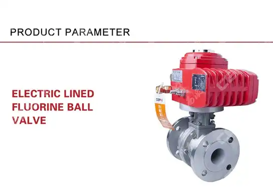
Electric Ball Valve systems represent sophisticated automation solutions that combine mechanical valve operation with electrical control mechanisms. These systems utilize electric actuators to rotate the ball within the valve body, providing precise flow control in applications ranging from HVAC systems to industrial process control. The Electric Ball Valve configuration determines both the mechanical flow path and the electrical wiring requirements, making proper understanding crucial for successful implementation. The fundamental operation of an Electric Ball Valve relies on the coordination between electrical signals and mechanical movement. When electrical power is applied to the actuator, it rotates the ball to either open, close, or redirect flow depending on the valve configuration. This automation eliminates the need for manual operation while providing remote control capabilities essential in modern industrial systems. The reliability of this operation depends heavily on proper wiring techniques that ensure consistent signal transmission and power delivery to the actuator assembly. Professional installation of Electric Ball Valve systems requires understanding both the mechanical aspects of valve operation and the electrical characteristics of the control system. The actuator assembly contains multiple components including motors, gears, position sensors, and control electronics, each requiring specific electrical connections. Proper wiring ensures these components receive appropriate power levels, control signals, and feedback information necessary for optimal performance.

2-Way Electric Ball Valve Wiring Configuration
The 2-way Electric Ball Valve represents the most straightforward wiring configuration, typically requiring three to five wires depending on the control requirements and feedback systems. Standard 2-way Electric Ball Valve installations use a three-wire configuration consisting of power supply (hot), neutral (ground), and control signal wires. The power supply wire, usually red or brown, carries the main electrical power to the actuator motor. The neutral wire, typically black or blue, completes the electrical circuit and provides the return path for current flow. The control wire in a 2-way Electric Ball Valve system determines the valve position based on electrical signals from the control system. In simple on-off applications, this control wire receives either 24V or 120V signals depending on the actuator specifications. When the control signal is present, the actuator rotates the ball to the open position, allowing full flow through the valve. Removing the control signal causes the actuator to return the ball to the closed position, stopping flow through the system. Advanced 2-way Electric Ball Valve installations may incorporate additional wires for position feedback, end-of-travel switches, and auxiliary contacts. Position feedback wires provide real-time information about valve position to the control system, enabling precise monitoring and control. These feedback systems typically use potentiometers or digital encoders that generate variable voltage or digital signals corresponding to ball position. Proper wiring of feedback systems ensures the control system can verify valve operation and detect potential malfunctions.
-
Safety Considerations for 2-Way Configurations
Safety considerations for 2-way Electric Ball Valve wiring include proper grounding, circuit protection, and emergency shutdown capabilities. Grounding wires must be connected to appropriate earth ground points to prevent electrical shock and ensure proper operation of safety systems. Circuit protection devices such as fuses or circuit breakers must be sized appropriately for the actuator current requirements while providing adequate protection against overload conditions. Emergency shutdown capabilities require additional wiring considerations in 2-way Electric Ball Valve installations. Spring-return actuators automatically close or open the valve upon power failure, requiring careful consideration of fail-safe positioning. The wiring must accommodate both normal operation and emergency conditions, often incorporating manual override capabilities that allow local valve operation during power failures or control system malfunctions.

3-Way Electric Ball Valve Wiring Systems
The 3-way Electric Ball Valve wiring system presents increased complexity due to multiple flow paths and positioning requirements. Unlike 2-way configurations, 3-way Electric Ball Valve systems require precise positioning to direct flow between three ports, necessitating more sophisticated control and feedback systems. The basic wiring configuration typically includes power supply, neutral, and multiple control wires that enable positioning the ball in various orientations to achieve desired flow patterns. Standard 3-way Electric Ball Valve installations utilize either L-port or T-port ball configurations, each requiring specific wiring approaches. L-port configurations connect two of the three ports in any valve position, requiring control signals that position the ball to select the desired flow path. T-port configurations can connect all three ports simultaneously or isolate individual ports, demanding more complex control logic and corresponding wiring arrangements. The wiring complexity of 3-way Electric Ball Valve systems increases significantly when incorporating position feedback and intermediate positioning capabilities. Many applications require the ability to position the valve at specific angles between fully open positions, enabling flow mixing or proportional control. This capability requires analog control signals and corresponding feedback systems that provide continuous position information to the control system.
-
Control Signal Requirements
Control signal requirements for 3-way Electric Ball Valve systems vary depending on the specific application and desired functionality. Simple applications may use discrete digital signals to select between predetermined positions, while complex process control applications require analog signals for precise positioning. The wiring must accommodate these signal types while maintaining signal integrity and preventing interference from power wiring or electromagnetic sources. Advanced 3-way Electric Ball Valve installations often incorporate programmable actuators that can be configured for various operating modes through digital communication protocols. These systems require additional wiring for communication buses such as Modbus, DeviceNet, or Ethernet/IP connections. Proper installation of communication wiring ensures reliable data exchange between the valve actuator and control system while enabling advanced diagnostic and configuration capabilities.
Step-by-Step Wiring Procedures
Proper wiring procedures for Electric Ball Valve installations begin with thorough preparation including system shutdown, component inspection, and wire preparation. Before beginning any electrical work, ensure all power sources are disconnected and properly locked out according to established safety procedures. Inspect the Electric Ball Valve actuator and associated components for damage or manufacturing defects that could affect wiring connections or system performance. Wire preparation involves stripping insulation to appropriate lengths, tinning stranded wires if required, and organizing wires according to the wiring diagram provided by the manufacturer. Use appropriate wire strippers to avoid damaging conductors, and ensure stripped lengths match terminal requirements to prevent excess exposed conductor or insufficient connection area. Quality wire preparation directly impacts connection reliability and long-term system performance. Connection procedures must follow manufacturer specifications regarding terminal torque, wire routing, and environmental protection. Tighten terminal screws to specified torque values using calibrated tools to ensure reliable connections without over-tightening that could damage terminals or wires. Route wires away from moving parts, heat sources, and potential damage points while maintaining appropriate separation between power and control circuits.
-
Testing and Commissioning
Testing procedures for Electric Ball Valve wiring begin with continuity checks using appropriate test equipment to verify proper connections before applying power. Check each wire connection against the wiring diagram to ensure correct routing and termination. Measure insulation resistance between conductors and to ground to verify adequate insulation and identify potential wiring problems before energizing the system. Functional testing requires gradual system energization while monitoring actuator operation and system response. Begin by applying control power and verifying proper actuator initialization sequences. Test each valve position to ensure proper ball rotation and flow path selection. Monitor actuator current consumption during operation to verify normal operation and identify potential mechanical problems or wiring issues. Commissioning procedures include calibrating position feedback systems, configuring control parameters, and documenting system operation for future reference. Position feedback calibration ensures accurate position indication and proper control system response. Control parameter configuration optimizes actuator performance for the specific application including operating speeds, torque limits, and fail-safe positioning.
Troubleshooting Common Wiring Issues
Common wiring issues in Electric Ball Valve installations include loose connections, incorrect wire identification, and improper grounding. Loose connections cause intermittent operation, overheating, and eventual failure of electrical components. Regular inspection and maintenance of electrical connections prevents these problems and ensures reliable long-term operation. Use thermal imaging equipment to identify overheating connections during routine maintenance procedures. Incorrect wire identification leads to improper operation, component damage, and potential safety hazards. Always verify wire identification against manufacturer documentation before making connections. Use wire markers or labels to identify circuits clearly, particularly in complex installations with multiple Electric Ball Valve units. Maintain accurate as-built documentation showing actual wire routing and connections for future troubleshooting and maintenance. Grounding problems cause erratic operation, electromagnetic interference, and potential safety hazards in Electric Ball Valve systems. Ensure proper grounding connections to appropriate earth ground points using appropriate grounding conductors. Verify ground continuity using appropriate test equipment and maintain ground connections free from corrosion or mechanical damage.
-
Electrical Safety Protocols
Electrical safety protocols for Electric Ball Valve installations require adherence to established lockout/tagout procedures, proper personal protective equipment, and appropriate test procedures. Always verify absence of voltage using calibrated test equipment before working on electrical systems. Use appropriate personal protective equipment including safety glasses, insulated tools, and arc-resistant clothing when working on energized systems. Emergency procedures must be established and communicated to all personnel working on Electric Ball Valve systems. These procedures should include emergency shutdown methods, emergency contact information, and first aid procedures for electrical accidents. Regular safety training ensures all personnel understand proper procedures and emergency response requirements.
Conclusion
Proper wiring of Electric Ball Valve systems requires comprehensive understanding of both electrical and mechanical aspects of valve operation. Following established procedures, safety protocols, and manufacturer specifications ensures reliable system operation while minimizing maintenance requirements and operational problems.
Cooperate with CEPAI Group Co., LTD.
CEPAI Group Co., LTD. stands as China's premier Electric Ball Valve manufacturer, combining advanced manufacturing capabilities with comprehensive quality assurance systems. Established in 2009 with 200 million yuan registered capital, our 56,000 square meter facility represents the pinnacle of intelligent manufacturing in the valve industry. As a national high-tech enterprise and specialized "little giant" company, CEPAI Group has earned recognition as a Jiangsu Smart Factory and Internet benchmark factory, demonstrating our commitment to technological innovation and manufacturing excellence.
Our Electric Ball Valve products undergo rigorous testing and quality control procedures, ensuring exceptional durability and high-precision control performance in demanding industrial applications. With API Q1, API 6A, API 6D, ISO 9001, and comprehensive international certifications, CEPAI Group delivers superior products that meet global standards. Our investment of 156 million yuan in intelligent manufacturing transformation has created the Asia Pacific region's longest high-precision flexible production line, enabling us to deliver customized solutions with unmatched precision and efficiency.
Partner with CEPAI Group for your Electric Ball Valve requirements and benefit from our extensive research and development capabilities, comprehensive technical support, and global service network. Whether you need standard configurations or customized solutions, our team of experts provides complete pre-sales consultation, installation support, and after-sales service to ensure optimal system performance. Contact our experienced engineers today at cepai@cepai.com to discuss your specific requirements and discover why leading companies worldwide choose CEPAI Group as their trusted China Electric Ball Valve supplier, China Electric Ball Valve manufacturer, and China Electric Ball Valve wholesale partner for High Quality Electric Ball Valve solutions at competitive Electric Ball Valve prices.
FAQ
Q: What voltage ratings are typically used for Electric Ball Valve systems?
A: Most Electric Ball Valve systems operate on 24VAC/DC, 120VAC, or 240VAC depending on application requirements and available power sources.
Q: How many wires are required for basic 2-way Electric Ball Valve operation?
A: Basic 2-way Electric Ball Valve operation typically requires three wires: power, neutral, and control signal.
Q: What is the difference between L-port and T-port 3-way Electric Ball Valve configurations?
A: L-port connects two ports while blocking the third, while T-port can connect all three ports simultaneously or provide various flow combinations.
Q: How often should Electric Ball Valve wiring connections be inspected?
A: Electrical connections should be inspected annually or according to facility maintenance schedules, with thermal imaging recommended for critical applications.
References
1. "Industrial Valve Automation and Control Systems" by Smith, Robert J., Engineering Technology Press
2. "Electric Actuator Wiring and Installation Manual" by Johnson, Michael A., Industrial Automation Publications
3. "Process Control Valve Selection and Sizing Guide" by Williams, Sarah K., Process Engineering Institute
4. "Electrical Installation Standards for Industrial Valve Systems" by Brown, David L., Professional Engineering Society
_1746598557316.webp)
Get professional pre-sales technical consultation and valve selection services, customized solution services.

About CEPAI


